-
What Is Fiber Termination Box?
Fiber termination box or fiber optic terminal box, which generally refers to a box shape cable management product used to protect and distribute the optical fiber links. It is small size and compact, used in FTTX cabling, including fiber cabling and cable management. Fiber termination box can be regarded as the mini size of fiber optic patch panel and ODF.

Types Of Fiber Termination Box
Usually the fiber termination boxes include fiber optic patch panel and fiber terminal box. Fiber optic patch panel is bigger size, while fiber terminal box is smaller. However, there are too many fiber optic termination boxes and cable management devices that it is hard to count their types. Many manufacturers will make the fiber optic termination boxes according to their own design and give the fiber optic termination boxes different names and model numbers.
Fiber Optic Patch Panels are usually 19 inch size. They can be wall mounted type or rack mounted type, and they have the tray inside the fiber box to hold and protect the fiber links. They can be pre-installed with various kinds of fiber optic adapters, which are the interface via that the fiber box will connect the external devices.
Fiber Optic Terminal Boxes are also used for fiber optic distribution and organization. Typical fiber terminal boxes are with 12 ports or 24 ports, with a size of 270mm*137mm*45mm. However, FiberStore can offer 8 ports, 36 ports, 48 ports and 96 ports fiber terminal boxes. They are made of cold rolling steel and the surface of the boxes use the technique of dim blowing plastic. They are typically installed with FC or ST adapters on the panel on the wall or put in horizontal line.
Fiber termination box types are mainly described as Rack Mount and Wall Mount:
Rack Mount Fiber Termination Box
The rack mount slide-out type fiber termination box performs fiber splicing, distribution, termination, patching, storage and management in one unit. They support both cross-connect and interconnect architecture, and provide interfaces between outside plant cables and transmission equipment.
Wall Mount Fiber Termination Box
The wall mount fiber termination boxes are designed for either preconnectorized cables, field installation of connectors, or field splicing of pigtails. They are ideal for building entrance terminals, telecommunication closets, main crossconnects, computer rooms and other controlled environments.
Fiber termination box types also include indoor and outdoor:
Indoor Fiber Termination Box
For example, FTTH floor terminal box is specifically designed to be installed on each level of a multi-dwelling unit (MDU) building for fiber to the home applications. It is the transition point between the riser and the horizontal cable and provides operators with optimum flexibility. It provides storage for both overlength and terminated fibers as well as serving as a splice point.
Outdoor Fiber Termination Box
The outdoor fiber terminal boxes are environmentally sealed enclosures to distribution fibers for FTTX networks. They are also designed for fiber splicing, termination, and cable management.
Structure Of Fiber Termination Box
Fiber termination box consists of the shell, the internals (supporting frame, set fiber disc, fixing device) and optical fiber joint protective element. It has advantages of cable-fixing, welding, and play protection role in machinery of the optical fiber and its components ,and environment.
Fiber termination box requires a insulation between cable metal components and cable terminal box shell, and can be easily drawn out of ground. It is able to provide a place of cable terminal and a room to storage the remaining fiber, easy to install, and having a sufficient impact strength box to be fixed, that facilitate the installation of different occasions. If necessary, it should have a function of connecting cable branching.
Applications Of Fiber Termination Box
Fiber termination box is suitable for fixing the end of fiber and splicing the fiber pigtail, meantime it protects fiber splice tie-in and helps to distribute fiber. Termination box is mainly used in telecom equipment room or network equipment room.
Fiber termination box is available for the distribution and termination connection for various kinds of fiber optic systems, especially suitable for mini-network terminal distribution, in which the optical cables, patch cores or pigtails are connected.
Article Source: Fiber Termination Box Tutorial
-
First of all, let us understand what an optical fiber is. Optical fiber is a fiber constructed of glass or plastic of a specific nature. It does not contain any metal material and thus avoids Electro-Magnetic Interference (EMI) and distortion of information along with the distance. This results in high accuracy of data along the transmission cable. The objective of fibre optic cable is to carry light waves along its length. The core technology for optical transmission is total internal reflection. Total internal reflection to ensures that the light is always along the body inner reflection material, so always keep a fiber in the body. As a result, the loss of signal is minimized, and hence the distance that the message can be carried without losing the signal is maximized. The light waves carrying the information along the channel have a path of propagation.
Multimode fiber optic cable can support the transmission of multiple paths of propagation with a higher amount of information at the same time. On the other hand, a single mode cable can only support a propagation path with a smaller bandwith. Because multimode cables carry higher amount of information at the same time, they have a higher diameter of the core used to carry the message compared to the single mode ones. Also, the higher diameter can make the multimode cables with higher transmission power. Usually multimode cables are used for short distance communications for usually a distance less than 500 meters, while single mode cables are popular for long distance communications.
Multi mode fiber optic cable has a large diametral core that allows multiple modes of light to propagate. Because of this, the number of light reflections created as the light passes through the core increases, creating the ability for more data to pass through at a given time. Because of the high dispersion and attenuation rate with this type of fiber, the quality of the signal is reduced over long distances. This application is typically used for short distance, data and audio/video applications in Local Area Networks (LANs). However, RF broadband signals cannot be transmitted over multimode fiber.
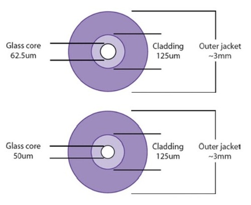
Multimode fiber cable is usually 50/125 and 62.5/125 in construction. This means that the core to cladding diameter ratio is 50 microns to 125 microns and 62.5 microns to 125 microns (shown as the figure). The transition between the core and cladding can be sharp, which is called a step-index profile, or a gradual transition. The two types have different dispersion characteristics and thus different effective propagation distance. Multimode fibers may be constructed with either graded or step-index profile, and those with graded index fiber is better in accuracy and performance. The numbers 50 µm and 62.5 µm refer to the diameters of the glass or plastic core, the part of the fiber that carries the light which encodes your data. The dimensions are sometimes specified as 50/125 μm and 62.5/125 μm, to include the diameter of the cladding. (The cladding confines the light to the core because it has a lower index of refraction.) Cable construction is shown in the following diagram, indicating the cable core, cladding, and outer jacket diameters.
Multimode fibers are identified by the OM ("optical mode") designation as outlined in the ISO/IEC 11801 standard.
- OM1 multimode fiber, for fiber with 200/500 MHz*km overfilled launch (OFL) bandwidth at 850/1300nm (typically 62.5/125um fiber)
- OM2 multimode fiber , for fiber with 500/500 MHz*km OFL bandwidth at 850/1300nm (typically 50/125um fiber)
- OM3 multimode fiber, for laser-optimized 50um fiber having 2000 MHz*km effective modal bandwidth (EMB, also known as laser bandwidth), designed for 10 Gb/s transmission
- OM4 multimode fiber , for laser-optimized 50um fiber having 4700 MHz*km EMB bandwidth designed for 10 Gb/s, 40 Gb/s, and 100 Gb/s transmission
Article Source: Multimode Fiber Optic Cables Tutorial
-
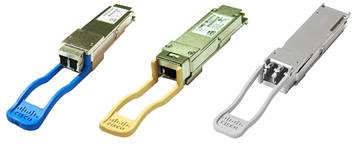
Are you still worrying about your slow network speed? No, there is a high speed transceiver. 40G QSFP+ transceivers make you enjoy the better transmission communications. As an essential component to support 40G network, QSFP+ modules which allow data rates of 4×10 Gbit/s to be emerged. This article is to introduce the 40G QSFP+ modules, include 40G QSFP+ cables and 40G QSFP+ transceivers. Fiberstore supplies high quality QSFP+ transceivers which are used primarily for short reach applications in switches, routers, and data center equipment.
What’s 40G QSFP+ Module?
The 40G QSFP+ module is a compact, hot-pluggable transceiver used for data communications applications. It supports Serial Attached SCSI, 40G Ethernet, QDR (40G) and FDR (56G) Infiniband and other communications standards. Compared with SFP+ modules, QSFP+ transceiver increases the port-density of 3-4 times.Main Products: 40G-SR QSFP+ & 40G-LR QSFP Modules on Fiberstore
The 40GBASE-SR4 is based on MMF (Multi-Mode Fiber) optic cable which is cheaper than SMF (Single-Mode Fiber) optic cable. It is able to transmit light in a relatively short distance. 40G QSFP+ SR4 transmission distance is between 100m and 150m.
The 40GBASE-LR4 with a pair of SMF optic cable provides two SC fiber optic connectors for connection. 40G QSFP+LR4 transmission distance is over 10km.
Table1: Fiberstore’s 40G QSFP+ modules order information:- QSFP-H40G-CU1M, 40GBASE QSFP+ Passive Copper Direct Attach Cable, AWG30, 1m, 0-70℃
- QSFP-H40G-CU3M, 40GBASE QSFP+ Passive Copper Direct Attach Cable, AWG30, 3m, 0-70℃
- QSFP-H40G-CU5M, 40GBASE QSFP+ Passive Copper Direct Attach Cable, AWG30, 5m, 0-70℃
- QSFP-H40G-CU7M, 40GBASE QSFP+ Active Copper Direct Attach Cable, AWG30, 7m, 0-70℃
- QSFP-4SFP10G-CU1M, QSFP+ to 4 SFP+ Passive Copper Direct Attach Breakout Cable, AWG 30, 1m, 0-70℃
- QSFP-4SFP10G-CU3M, QSFP+ to 4 SFP+ Passive Copper Direct Attach Breakout Cable, AWG 30, 3m, 0-70℃
- QSFP-4SFP10G-CU5M, QSFP+ to 4 SFP+ Passive Copper Direct Attach Breakout Cable, AWG 30, 5m, 0-70℃
What are features of 40G QSFP+ Modules?
1). Hot-pluggable input/output device that plugs into a 40 Gigabit Ethernet QSFP port
2). High-speed electrical interface compliant to the IEEE 802.3ba standard
3). Certified and tested on QSFP 40G ports for superior performance, quality, and reliability
4). Digital Diagnostics Monitoring InterfaceBesides its high-density applications, QSFP+ modules provide 40Gb/s Ethernet data rates over MMF (Multi-Mode Fiber) optic cable and SMF (Single-Mode Fiber) optic cable. QSFP+modules take up very little space on a switch or server interface, allowing vendors to provide multiple QSFP+ ports in the same space.
How about the 40G QSFP+ modules’ Market?
With the increasing demands of global Internet traffic, higher requirements are concentrated on the network communications transmission capacity. The market research shows that the whole communication network is in urgent need of the optical transmission bandwidth upgrade from the original 10G to 40G and 100G. Data Center Construction requires the higher bandwidth and port-density for modules. Therefore, 40G QSFP+ modules have a huge overseas sales market, such as Facebook, Google, Cisco and so on. It means that QSFP+ transceiver modules have a good future.About Fiberstore:
Fiberstore is devoted to design, manufacture, and sell a broad portfolio of optical communication products, including Cisco QSFP+ modules, QSFP+& CFP transceivers, 40G QSFP+ cables and transceivers, QSFP+ loopback transceivers, and QSFP+ breakout cables. votre commentaire
-
HP X121 1G SFP LC Transceiver Models
- HP J4858C 1000BASE-SX SFP 850nm 550m LC Transceiver
- HP J4859C 1000BASE-LX SFP 1310nm 10km LC Transceiver
- HP J4860C 1000BASE-LH SFP 1550nm 70km LC Transceiver

HP X121 1G SFP LC SX Transceiver (J4858C)
HP J4858C - 1000BASE SX transceiver that provides a full-duplex Gigabit solution up to 550 m on multimode fiber.
- Ports: 1 LC 1000BASE-SX port; Duplex: full only
- Wavelength: 850nm
- Cable length: 2-550m
- Cabling Type: 2.5/125 μm or 50/125 μm (core/cladding) diameter, graded-index, low metal content, multimode fiber optic, complying with ITU-T G.651 and ISO/IEC 793-2 Type A1b or A1a, respectively
- Maximum distance:
2-220 m (62.5 μm core diameter, 160 MHz*km bandwidth)
2-275 m (62.5 μm core diameter, 200 MHz*km bandwidth)
2-500 m (50 μm core diameter, 400 MHz*km bandwidth)
2-550 m (50 μm core diameter, 500 MHz*km bandwidth)
HP X121 1G SFP LC LX Transceiver (J4859C)
HP J4859C - 1000BASE SFP LC LX Transceiver: An SFP format gigabit transceiver with LC connectors using LX technology.
- Wavelength: 1310nm
- Ports: 1 LC 1000BASE-LX port (IEEE 802.3z Type 1000BASE-LX); Duplex: full only
- Cabling Type: Either single mode or multimode; 62.5/125 μm or 50/125 μm (core/cladding) diameter, graded-index, low metal content, multimode fiber optic, complying with ITU-T G.651 and ISO/IEC 793-2 Type A1b or A1a, respectively; Low metal content, single-mode fiber-optic, complying with ITU-T G.652 and ISO/IEC 793-2 Type B1;
- Maximum distance:
2-550 m (multimode 62.5 μm core diameter, 500 MHz*km bandwidth)
2-550 m (multimode 50 μm core diameter, 400 MHz*km bandwidth)
2-550 m (multimode 50 μm core diameter, 500 MHz*km bandwidth)
2-10,000 m (single-mode fiber) - Note: A mode conditioning patch cord may be needed in some multimode fiber installations.
HP X121 1G SFP LC LH Transceiver (J4860C)
HP J4860C - Gigabit LH transceiver that provides a full-duplex Gigabit solution up to 70 km on single-mode fiber.
- Wavelength: 1550nm
- Ports: 1 LC 1000BASE-LH port (no IEEE standard exists for 1550 nm optics); Duplex: full only
- Cable type: Low metal content, single-mode fiber-optic, complying with ITU-T G.652 and ISO/IEC 793-2 Type B1;
- Maximum distance: 10-70,000 m (single-mode fiber)
- Note: Power consumption is 0.8 watts typical with 1 watt maximum at 100% utilization.
For distances less than 20 km, a 10 dB attenuator must be used.
For distances between 20 km and 40 km, a 5 dB attenuator must be used.
Attenuators can be purchased from most cable vendors.
OEM Manufacturer
HP SFP transceivers offered by Fiberstore are third-party optical modules certified fully compatible with HP Switches & Routers. The HP SFP modules can be mixed and deployed with HP OEM SFP transceivers for seamless network performance and interoperability. Fiberstore provides HP compatible SFP transceivers which can be equivalent to HP JD118B, HP JD092B, HP JD089B, HP J9143B, HP J8177C, etc.
votre commentaire
-
Introduction
Use a transceiver module for connection to a remote device. The SFP (also known as mini-GBIC) and SFP+ transceiver modules are hot swappable. This means that you can install and remove a module while your device is operating. The SFP and SFP+ modules provide duplex single-mode or multi-mode connections. SFP Transceiver Modules The SFP module uses 3.3V power input and either duplex LC-type connectors or RJ-45 connector (e.g. HP J8177C). SFP+ Transceiver Modules The SFP+ module uses single 3.3V power input and duplex LC connector interface.
Note: SFP and SFP+ are static sensitive. To prevent damage from electrostatic discharge (ESD), it is recommended you attach an ESD preventive wrist strap to your wrist and to a bare metal surface when you install or remove a SFP or SFP+ module. SFP and SFP+ modules are dust sensitive. When not in use, always keep the dust plug on. Avoid getting dust and other contaminant into the optical bores, as the optics do not work correctly when obstructed with dust.
Note: Optical SFP and SFP+ modules are equipped with a Class 1 laser, which emits invisible radiation. To avoid possible eye injury, do not look into an operating fiber-optic module's connectors. Laser radiation is present when the device or system is powered up. Only trained and qualified personnel should be allowed to install or replace these modules.
Installing and Removing an SFP/SFP+ Module
This section describes how you install and remove a SFP or SFP+ transceiver module.
Note: Disconnect all fiber-optic cables from an SFP/SFP+ module before installing or removing it. Do NOT remove and install an SFP/SFP+ module more often than is absolutely necessary. Doing so may shorten the useful life of the SFP/SFP+ module.
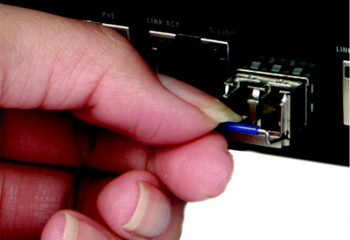
Installing an SFP Module
Follow the steps below to install an SFP/SFP+ module.
- Attach an ESD preventive wrist strap to your wrist and to a bare metal surface.
- Remove the SFP/SFP+ module from its protective packaging.
- Locate the transmit (Tx) and the receive (Rx) markings on the SFP/SFP+ module.
- Align the SFP/SFP+ module in front of the slot opening on a device.
- Insert the SFP/SFP+ module into the slot until the SFP/SFP+ module snaps into place

Note: SFP/SFP+ module installation orientation varies depending on your device. Your SFP/SFP+ module comes with a mechanism that prevents incorrect insertion. Do NOT force or twist the SFP/SFP+ module into a slot.
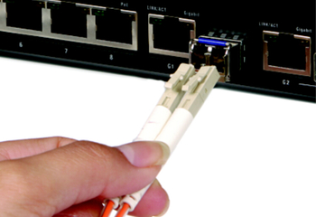
Connecting a Fiber-optic Cable
Follow the steps described to connect a fiber-optic cable to the SFP/SFP+ module.
- Remove the dust plugs from the SFP/SFP+ module and the cables.
- Identify the signal transmission direction of the fiber-optic cable and the SFP/SFP+ module. Insert one end of the fiber-optic cable into the SFP/SFP+ module.
- Insert the other end of the fiber- optic cable into a remote device.
Refer to the user’s guide that comes with your device for SFP/SFP+ module slot status.
Removing an SFP/SFP+ Module
Follow the steps below to remove an SFP/SFP+ module.
- Attach an ESD preventive wrist strap to your wrist and to a bare metal surface on the chassis.
- Disconnect all fiber-optic cables from the SFP/SFP+ module.
- Insert the dust plug into the ports on the SFP/SFP+ module.
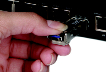
- Pull out the latch and down to unlock the SFP/SFP+ module.
- Using your thumb and index finger, grasp the tabs on both sides of the module and carefully slide it out of the slot.
Note: Do NOT force or twist the module out of a slot.
All of the guidelines above are also applied to Cisco SFP modules.


|
|
|
|